LONGRICH POWER ENGINEERING TEST METHOD

Grounding Continuity Test for Travel Adapters.

True grounding requires a continuous protective-earth path through the adapter. A grounding continuity test checks whether the destination-side earth contact, internal conductor and appliance-side earth contact are electrically connected as designed.

Key point: a visible third pin does not prove functional grounding. The earth path must be electrically continuous and mechanically reliable through the complete adapter system.
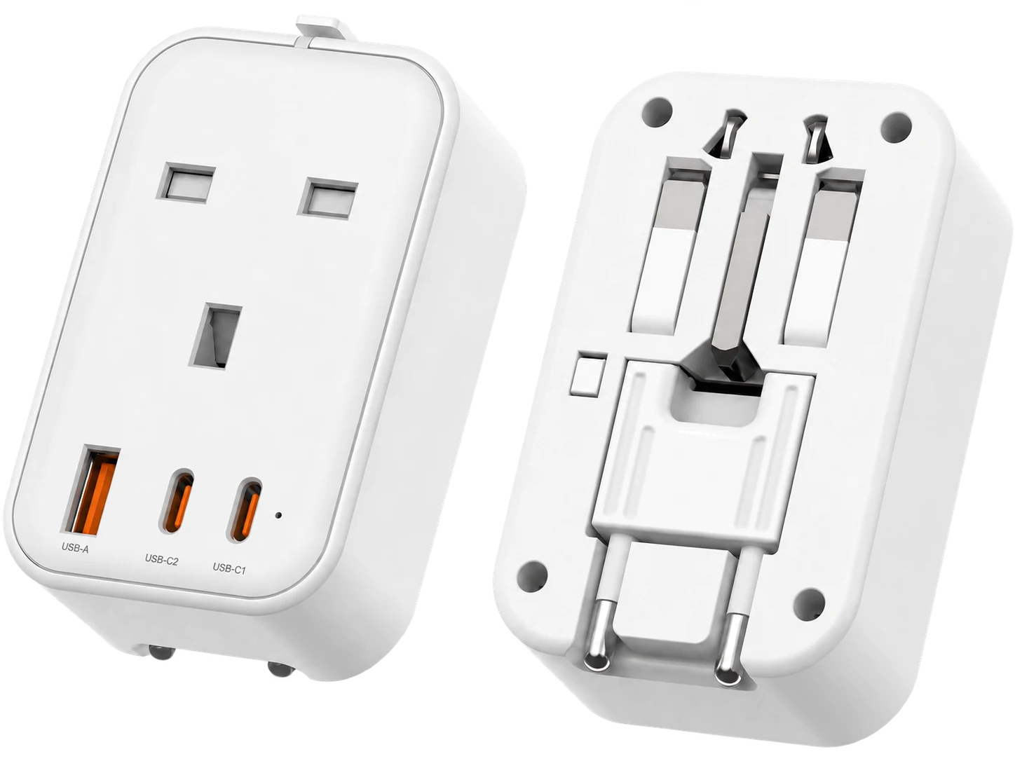
NT009-UK grounded travel adapter continuity test platform

What the Test Verifies

Input Earth Connection

Verify that the destination-side earth pin or earth contact is conductive and connected to the intended internal grounding path.

Internal Ground Path

Verify continuity through the internal metal parts or conductor system used to carry protective earth.

Output Earth Contact

Verify that the appliance-side earth contact is electrically connected to the same grounding path.

Mechanical Reliability

Check that grounding contact remains reliable after plug deployment, insertion and repeated product use.

Typical Test Flow

01 — Identify Earth PointsLocate the destination-side earth contact and appliance-side protective-earth contact.
02 — Connect Test InstrumentMeasure continuity across the intended protective-earth path.
03 — Check Contact StabilityConfirm the reading remains stable while the plug mechanism is fully deployed and seated.
04 — Repeat After Mechanical CyclingRecheck continuity after insertion, removal or durability cycling where required.

What B2B Buyers Should Ask for

Verification ItemWhy It Matters
Earth-path diagramShows the intended route from input earth to output earth.
Continuity test methodConfirms the supplier is testing electrical continuity rather than only visual structure.
Measurement pointsDefines exactly which contacts are being tested.
Mechanical cycling conditionShows whether grounding remains reliable after repeated plug use.
Applicable pass criteriaShould be defined by the final product design, customer specification and relevant standard.

Why UK Type G Needs Special Attention

UK Type G plugs use a longer earth pin and socket shutter system. In some products, a third pin may mechanically open the shutter without providing protective-earth continuity. A grounded adapter must therefore be evaluated for both the mechanical function and the electrical earth path.

Grounding Is Not the Same as Voltage Conversion

A grounded travel adapter can provide protective-earth continuity while still leaving the mains voltage unchanged. Grounding, plug adaptation and voltage conversion are separate product functions and should be specified separately.

Current Public Data Status

No fabricated resistance value: LONGRICH has not published a numeric grounding resistance or continuity threshold on this page because the exact project test record, instrument and acceptance criterion have not yet been provided for public release. The page documents the engineering method and verification logic only.

Frequently Asked Questions

How do you know whether a travel adapter is truly grounded?

By verifying electrical continuity from the appliance-side earth contact through the adapter to the destination-side earth connection.

Is a third pin enough to prove grounding?

No. A third pin can be mechanical only. Functional grounding requires a continuous conductive earth path.

Should grounding be retested after mechanical cycling?

Yes, where appropriate. Repeated plug use can affect contact reliability, so post-cycling verification is useful.

Does this page claim a specific grounding resistance?

No. A numeric acceptance value is not published until the relevant internal test record and applicable criterion are confirmed.